Power Supply of the Transrapid Vehicle
This article explains in detail how the Transrapid vehicle is supplied with power.
As is well known, the Transrapid has no overhead lines. Yet the energy demand of all onboard consumers, such as the levitation/guidance magnet modules or the lighting in the passenger cabin, still has to be met. This article explains how and from where the Transrapid obtains the energy it needs during normal operation.
Power supply
During normal operation, power is supplied to the vehicle by 160 linear generators per section and by power rails or, on newer vehicles such as the TR09, Inductive Power Supply.
From roughly 20 km/h, the linear generators begin to produce energy. At 20 km/h, however, they generate too little. From 30 km/h, the energy generated is already enough to cover the demand of low-voltage consumers, including pneumatics, safety circuits and the test of the eddy-current brake. From about 70 km/h, the energy generated is enough to cover the demand of the levitation magnets. From about 100 km/h, it is enough to cover the demand of the guidance magnets as well. This means that the entire energy demand of the section is covered from 100 km/h.
Only for the maximum output of the air conditioning and the eddy-current brake is the energy at 100 km/h not yet sufficient. That does not mean, however, that air conditioning and eddy-current brakes do not work at 100 km/h. They continue to be buffered by the nickel-cadmium batteries on board.
The eddy-current brake is merely the Transrapid’s emergency brake, installed in the vehicle. Unlike the service brake, which is generated by the linear motor in the guideway, eddy-current braking does not feed any energy back into the public grid or into braking resistors. On the contrary, the vehicle supplies the power for the emergency braking process entirely by itself.
The energy generated by the linear generators is rectified by several boost converters per section and fed directly into the Transrapid’s various onboard power networks.
Before the speed of 100 km/h is reached, however, an additional power supply is necessary.
Additional power supply
Newer vehicles such as the TR08, TR09 and CRRC 600 are fitted with additional power supply systems.
Power rails are used on the TR08 and CRRC 600. The power rails supply the vehicles with 400 V direct current. For this, the vehicle extends its mechanical current collectors at speeds from 0 to 100 km/h, which then make mechanical contact with the guideway. In this way, the vehicle is supplied with energy before it reaches a speed of 100 km/h. At speeds above 100 km/h, power rails are unnecessary.
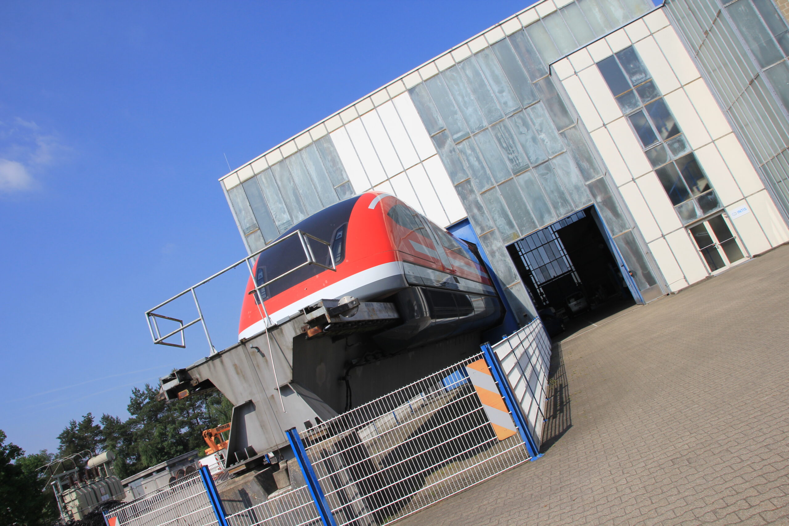
Inductive Power Supply (IPS) is used on the TR09. The system was developed jointly with the Technical University of Braunschweig to provide a secondary power supply for the vehicle without requiring mechanical contact with the guideway (as with the power rails). The system uses 400 V alternating current at a frequency of 20 kHz, which enables contactless energy transfer to the secondary coil in the vehicle. A modified, adapted version of this technology is being pursued by INTIS. INTIS has adapted the system to other electric vehicles, so that electric cars, e-buses and e-scooters can also benefit from it. The advantage is that a very high efficiency is achieved, and charging is no slower than with a cable, in some cases even faster.
It should be noted that the Transrapid’s onboard networks are buffered by a nickel-cadmium battery. This means that a (brief) absence of power rails or IPS below 100 km/h does not cause a loss of levitation or any other restrictions. The TR06 and TR07 had no secondary power supply; at stations the vehicles simply charged their batteries via a cable. The systems just mentioned (power rails and IPS) are also needed in emergencies to secure the vehicle’s power supply. For the TR06 and TR07, towing exercises were therefore carried out on the TVE with special vehicles that drove up to the vehicle in an emergency and supplied it with power. For this purpose, both vehicles (TR06/TR07) had removable flaps at the front, behind which the connections for the power supply were located. From the TR08 onward, towing is no longer required, since power rails were installed along the line. In 2005, the IPS system was tested on the TVE for the first time, though not with the TR09 but with the TR08. For this, the corresponding secondary coil was installed in E2 (end section 2) on one TFMM (levitation and guidance magnet module). The tests proved that the system works at least as reliably as the mechanical contact with power rails, as used natively on the TR08. In China, however, CRRC is not relying on IPS for its newest vehicle, since CRRC does not hold the licenses for it. It should also be noted that of the 29.9 km SMT line in Shanghai, 23.8 km are equipped with power rails. In theory, this would increase the compatibility of the CRRC 600 with the SMT line, apart from the incompatible operations control system.
The Transrapid's onboard power networks
Each vehicle section has three different onboard power networks: four mutually independent 440 V (direct current) networks per section, four mutually independent 24 V networks, and one 230 V network. This gives a particularly high level of redundancy, which ensures the Transrapid’s safety even during power outages.
The 4x 440 V networks feed the levitation/guidance magnets, the eddy-current brake and the air conditioning. As mentioned above, these networks are buffered by a nickel-cadmium battery.
The 4x 24 V networks feed the safety-relevant consumers of the vehicle section, including vehicle control, operations control and communication components. The 24 V networks are fed redundantly (with multiple safeguards) from the 440 V network.
The 1x 230 V network feeds the consumers in the passenger cabin, including passenger information, lighting and, by today’s standards, (USB) sockets with which passengers can charge their devices. The CRRC 600 does in fact have USB ports built into first-class seats for charging devices. This is an alternating-current network at a household frequency of 50 Hz, which is also fed from the 440 V network via inverters.
Naturally, all of the Transrapid’s onboard networks and battery circuits are designed to be ground-fault and short-circuit proof. As mentioned above, these networks are buffered by batteries. Typically the networks are fed by the boost converters and linear generators, but also by an energy source in the vehicle, the batteries.
Thanks to this high redundancy, a total power failure is therefore impossible. More than 25 million kilometers traveled by the system in Shanghai confirm the high redundancy and an MTBF (mean time between failures) of at least 35 years (for the TR08).